Weber Air Horn question

team-gpracing":1x75lv13 said:
I know that the air horns on the Weber serve an important purpose that basically cleanly channels the air straight into the carb, but should I remove the horns when used in conjunction with the assembly and air box? The cover of the airbox/K&N assembly only sits about an inch above the top of the horns, and all of the air comes from the ducting, into the airbox and through the filter to the side of the horns. Again, I know they serve a purpose, but I also think that the flow of air would be much less restricted if I removed them. Especially at speed when the two 4"d hoses are really feeding the airbox.

I plan on trying it the next time I go to the dyno, but I'm not sure that will give me accurate results (fans only do so much). Any thoughts from the engineers (with degrees and otherwise) on the forum?

When you are on the dyno, test the air gap you have on your new air box, with and without the air horns. Test it again without the lid, with and without the air horns.

The finish and radius of your air horn inlet, the length of the air horn, air pressure at the air horn, and air gap between the lid and air horn inlet, all will affect your results. If the air gap between the horn and top lid is too small you will reduce air flow and increase inlet turbulence. Putting spacers between your manifold and engine can also affect dyno results. It all depends on how much space you have between the hood and the engine.
 
I've done some research and it seems that velocity stacks are indeed important (I figured as much). The real question though is whether the proximity to the cover is more of a negative effect than removing the stack. I'm going to purchase a set of "shorty" stacks and test all three (stock/short/none) the next time I'm on the dyno. I'll let you know what I find.
 
the proximity to the airbox lid is the key.. yes it will eventually cause a loss in power, but where's that threshold? 1x choke diameter? 1/2 choke diameter? would definitely be nice to know.

When I was modifying my airbox, I had about 2" above the stacks. I was able to find a taller 10" round K&N filter that fit inside the box by about 1/4" and left plenty of clearance for the horns.
 
I seem to remember reading that on the 4 rotor prototypes, variable length trumpets (would that make them trombones?) were used.
 
:applause: Trombones. I've heard about those as well. I believe the RX8s utilize something like that with their intake system.
 
Greg Nagy":25d4vx50 said:
I seem to remember reading that on the 4 rotor prototypes, variable length trumpets (would that make them trombones?) were used.

The 787B had them, so did some Formula 1 engines, and some sport bike engines have them. Most of them have been outlawed in racing.

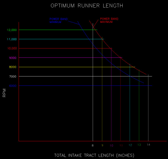
runnerlength2.jpg


To measure your intake port length, use a length of electrical solder. Straighten the solder and lay it in the port along the floor. Mark it at the valve seat and the manifold gasket face. Straighten it back out and measure between the marks. Repeat for the roof, positioning the solder next to the valve guide. The average of the two measurements is your port length. A ¼” tape measure can also be used instead of solder.

Use the same method to measure the manifold runner length, but don’t wrap the solder or tape measure around the plenum radius. Just extend it tangent to the runner wall, and measure to a straight-edge running across the top of the runners. Most engine builders use the average of the front and back walls of the runner, but some use the floor and roof. It is common to have two or more different runner lengths in a manifold. If so, use an average length for the next calculation.

Add the average runner length, average port length, and manifold gasket thickness, and you have the total intake tract length.

Example: You have an engine with a 6.25 inch average port length. You want the engine to operate between 8500 and 9500 RPM. From the graph above, you need a total intake tract length of about 10.5”. That leaves 4.25 for the runner length and gasket. With a 0.06” gasket, the average runner length should be 4.19”.

From http://www.swartzracingmanifolds.com/
 
This is from a book on tuning A-series engines(Minis & Co). It's the only comprehensive comparison of Weber stack lengths I have ever found. Hope it helps.
 
That's a page from David Vizard's book. Believe these numbers were observed on a flow bench. Understand there's similar results on the dyno, but think the reverse impulse resulting from radical cam overlap has an effect. ???

Still think 2 venturi diameters clearence in front of the stack is the minimum.

RJS
 
After watching this thread for a few days, some thoughts:

Shorter stacks will probably give less performance, longer may give more. I suggest making adjustable length or several trumpets to try on dyno day.

The length of the entire intake runner to each rotor (or cylinder) is very important to torque and horsepower. Inertial and pressure pulse tuning are both affected by the length of the runners. Too many variables are at play to reliably calculate the best length. The pressure pulses in a tapered runner behave as though the runner is shorter than it's actual length. Books have been written about other variables. Bottom line - you just have to try different lengths that are do-able and use the one that gives the best torque curve. Bring a fuel jet selection too. More air needs more fuel.

On the topic of open space at the trumpet opening, the policy I favor is a MINIMUM of 1 1/2 times the diameter of the trumpet mouth to the roof or wall of the box or filter top plate. With a carb over a plenum, a little less space may be needed, since airflow is nearly constant instead of starting and stopping every intake cycle as with your isolated runners. The "standoff" mentioned in the post above is what happens when the closed valve or rotor side slams the door in the face of the air/fuel whistling down the intake tract at several hundred feet per second. It hits the dead end, compresses, springs back, and some of it shoots back out the mouth of the trumpet before the next suck event.

On the topic of cool air and airbox pressurization, concentrate on cooling the carb, manifold, and incoming air. According to data from a "How to Build Horsepower" course given by the above mentioned David Vizard, pressurization from an optimally designed forward facing hood scoop (as on a Pro Stock car) can only gain about 1% power at 90 mph and 2% at 130. Cooling the air entering the cylinder (or rotor chamber) gains you about 1% for every 10 deg. F cooler. By cooling the whole carb you can gain 2% (20 deg.) and more all the time, instead of only at top speed.

On my GT3 RX2, I built an airbox with the floor of the box sandwiched between the carb and manifold, put a 1 1/2 in. foam rubber square seal on the top of the box walls (window unit AC seals from Home Depot), and used the car hood for the top of the box. This put the whole carb in the cool air and left maximum space over the trumpets (allowed a very tall air filter).Have fun on dyno day. IMO, successful development is much of what makes Production and GT more fun than spec. The effectiveness of the airbox and ducts, though, will have to be tested by on-track performance, such as segment times for a long straight.

And yes, per that recent post, the shape of the lip is important, too. The air wants to rush in from every direction it can.

Enough! My fingers are tired.
 
Great info guys. I am hitting the track for a test day this weekend and I have a couple different stacks to plug onto the carb. I have a data acquisition system that should give me an idea of how the changes effect the car (without giving me hp).

Tom W":yy6wl6gi said:
IMO, successful development is much of what makes Production and GT more fun than spec.

Agreed. That's one of my favorite aspects of Prod. The experimental science and engineering.
 
As your horn (and therefore your intake tract) lengthens, your torque peak tends to move down the rpm range. This may result in a loss of peak horsepower at higher rpm, but can give you more "power under the curve," so to speak, and help your torque curve overall.

Tom W":1z602j4t said:
The "standoff" mentioned in the post above is what happens when the closed valve or rotor side slams the door in the face of the air/fuel whistling down the intake tract at several hundred feet per second. It hits the dead end, compresses, springs back, and some of it shoots back out the mouth of the trumpet before the next suck event.

As a side note - "standoff", or reversion, is actually caused by the intake valve closing too late after BDC on the compression stroke. The problem with reversion is that the fuel/air mixture goes back through the carb on the next intake cycle, and gets more fuel added, causing a rich condition. Obviously, you need the extra duration at higher rpm (the inertia of the intake flow at higher rpm is enough to overcome the reversion, so more mixture is trapped in the cylinder) but lower rpm suffers because of this. That's one of the things that variable valve timing fixes. As a side note, if the intake tract length is correct, the reflected pulse from the open end of the air horn (which is the second order reflection of the pulse caused by the closing of the intake valve referred to by Tom W) can be timed to arrive back at the intake valve at the rpm range where reversion begins, and help mitigate the problem.
 
Back
Top