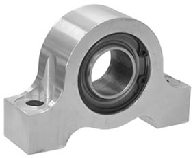
Really big monoball housing?

blamkin86

Well-known member
Hi folks - I am looking for a monoball/bearing housing - one that has snap rings on either end.

Here's a few examples: http://ubmachine.com/monoballhousings.html
48-1211.jpg


The size of the monoball is 2.375" OD.

This is for a swaybar mount. I'm ultimately trying to tig together something like this, but for a 1.25" bar:
http://www.colemanracing.com/Sway-Bar-B ... P3668.aspx
20383.jpg


I realize I can just use the typical bearing-less pillowblocks, or some sort of urethane bushing -but I want to explore this avenue first.

Thanks in advance.
--Bill
 
blamkin86":2tq6tlv3 said:
Dick those are smaller than what I'm looking for.

http://secure.chassisshop.com/partlist/6455/

The biggest is 1-7/16 ID and I need 2-3/8.

I shot an eMail off to UBMachine to see if they would fab me one within cost reason.

I searched for the same thing many years ago and never found them. I ended up
having them made. If you go that route, my first call would be to
http://www.mechspecial.com/
Make a drawing and give Gene a call. Drawing doesn't need to be CAD, just
something simple. Gene (GT2 Crew chief and talented prototype machinist)
will know what you are after.
 
Awesome thanks Kevin. Thought I was going nuts.

I'm going to go ahead and call UBMachine while I'm at it.

I was considering this stuff: http://store.drpperformance.com/product ... CETAL.html

...but that, like what I have already, doesn't allow for any misalignment or thrust between the two bearings.

Another alternative is to go the circle track route, and mount a bar housing that has those two bearings on its ends (to alleviate any misalignment)... but I really don't want to add the weight of the bar housing out front like that.
 
Kevin - I think (correct me if I'm wrong) the inner race cannot get out of alignment with the outer housing, without binding up.

Doesn't seem like a normal need of a swaybar mount, but I've been fighting a bizarre binding problem and figured the spherical bearing was the way to go. That way if something is moving around, the bar would still rotate.
 
True, race to race no movement. The picture I posted is a bearing out of self aligning pillow block. Outer race moves within the housing. Traditionally the housings are cast and big, but I have seen some 2 bolt flange style housings that are very compact. Just a thought.
 
You said you are replacing part number 605-125s. Are you using a 1.25" diameter bar?

Why are you replacing 605-125s, with your fabricated part? Is the old one squeezing out the black flexible liner?? That is an indicator that the mounting points (left and right) are not remaining aligned with the axis of a straight sway bar.

Also said you had a binding problem. Can you describe that a little better? Is the handling changing, or are you seeing the binding in the shop, as you jack the suspension up & down?

You may want to see where the sway arm is possibly contacting another suspension arm and causing the binding? Or, you may also evaluate to see if the frame horns/mounting brackets for the pillow supports are flexing, and distorting the alignment between the left & right sway bar mounts.

I used the same type of pillow mounts in an older GT1 car, and needed to strengthen the frame horns supporting the mounts. My indicator was the black flexible liner was being squeezed out of the housing.

If it is chassis flex, and not corrected, it is possible that a stronger bar mount will result in bending your sway bar or arms. Then the handling gets even stranger.... The stress will no longer be absorbed by the stronger pillow mounts. But, by the bar that may be forced to bend, if the new mounts don't snap first! If the chassis flex is very minimal, or strengthing the chassis not an option, consider putting some thin rubber spacers between the pillow mounts and their mounting points. Consider it a small, fifth, suspension spring, and tune around it!! It will be compressed enough to allow the mounts to stay closer to alignment. It should place them closer to alignment when they are loaded in a turn.
 
OK, this is somewhat embarrassing, except it was a great lesson. I guess I'm embarrassed how long it took to figure out, but not surprised. I'm over my head building this thing but getting better every weekend in the garage.

So... _WAY_ back in '07 when I first started building this car, I knew almost nothing about suspensions or welding.

Basically, I started with these mounts from ISCRacing (these are upside down and not mounted):
sway%20bar%20mounts.bmp


They mount in the stock location, like so:
SB%20Mount1.JPG


Unfortunately, back then, I had no idea about such things, and simply welded them on willy nilly. Heck the welds are just awful.

Anyway, my cars' handling has never ever been close to what it should be. I tried different shocks, springs, all sorts of suggestions. Then, at one event, I accidentally left the front bar loose, and voila! The thing was transformed.

Over that winter, I decided that my bar must be too big, so I bought the smallest Speedway Engineering bar they make. Unfortunately, the small bar didn't help at all.

I never even thought there could be a problem with the mounts; I just never considered it.

Anyway, I am doing a major once over on the suspension, including measuring everything and entering it into WinGeo3.

About a month ago, as I was measuring everything, I looked over my swaybar, and found the following:
1) Passenger side end link bolt - the nut was bottoming out on the bolt shank, instead of tightening down the end link. The bar has about a 1" zone where it was ostensibly unhooked.
2) The two inside swaybar collars were moving 1/4" inboard from both sides, during a race... and to move like that, they must be jammed up against the bearing at some point.
3) I welded the driver's side bearing mount parallel to the ground - but passenger side is at about a 15* longitudinal angle - meaning when I tighten down both bar mounts, you can't really turn the bar.

So, I can probably use the bearings again... but I just want to start over. I have no faith in them.

The way out is to carefully TIG together some sturdier mounts, put the bar through the bearings on both those mounts, and MIG the mounts on the frame horns while everything's square; tightening as I go to be sure everything lines up and doesn't bind.

I figured some sort of (different) spherical bearing would let there be a slight misalignment without binding.

As to what you're suggesting - it's possible the unibody or frame horns are bending as you suggest - but unlikely. The subframe is bolted about 10" in front of the two mounts. To bend, the subframe would have to bend a lot...

...not saying it isn't happening.

Anyway, lesson learned. I'm better for figuring it out.
 
I don't see any distortion of the brackets. Are welds cracking? Are bolts loosening or breaking? Any shiny spots on bolt or thread contact areas? How is bar adjusted and aligned. With the suspension loaded to it's normal ride height, Is the bar at the highest point of it's arc? Are the links at the highest point of their arcs.
I believe the brackets are adequate for that setup. You said it handled better when the link loosened. That means the bar had been looser. You might have more bar than you need.
With the car loaded at ride height, the bar should be completely unloaded. You should feel no resistance when turning the links. I'd lose the slider link and replace it with a flat arm with adlustment holes. If it's setup right, you could almost move it by hand. I'd lose those flimsy looking pillow blocks and go with the aluminum billet pillow blocks with no bearings. Bolt them to the gusseted and rewelded brackets. The billet blocks are available from the circle track crowd. Make the bolt holes for at least one of the brackets, a bigger diameter, so the pillow block will be alignable to the other. You'll need to keep these greased up as there's no bearing.
Lets' see the links and control arm in loaded position. It's more likely that you've got something binding or not aligned properly as it moves through it's travel. If you are able to disconnect one link and then move that bar through it's range of travel, then you are in good shape. You can gain in roll resistance by having proper geometry and thus not needing a stiffer bar. Also take leverage of the arms into account. Get the proper length arms to achieve the best movement from the control arm.
 
loopracing":17sq776a said:
I don't see any distortion of the brackets.
Sorry - those pix are from the ISC racing website - they are not the exact brackets nor even my car.
loopracing":17sq776a said:
Are bolts loosening or breaking?
Yes, as a matter of fact the bolts holding the bearing to the misaligned mount come loose a lot.
loopracing":17sq776a said:
How is bar adjusted and aligned. With the suspension loaded to it's normal ride height, Is the bar at the highest point of it's arc? Are the links at the highest point of their arcs.
This one I don't quite understand. With the car race ready, the ends of the arms with the endlinks are pointing slightly upward. The highest point of the arms arc is when the suspension is fully compressed.
loopracing":17sq776a said:
I'd lose the slider link and replace it with a flat arm with adlustment holes. If it's setup right, you could almost move it by hand.
Can you explain what you mean by slider link?

Thanks for your input. To reiterate, the mount on the passenger side is welded at an odd angle to the ground. When you put just the bar, with no arms, through the bearings and tighten them down - because of this odd angle the bar binds against the two bearings and you can't turn it by hand.
 
You described a clamp coming loose. I took that to mean that the links have a clamp around the sway bar end that slides for adjusting tension, no?
Also use the good "drill stop" collars on both sides of the bearings in order to locate the bar from sliding side to side.
 
I would definitely fix the binding problem, then revisit the rest of the stuff from there. I'm lucky that the stock mounting locations on my car are pretty good and are part of the frame horns- everything is nice and square, and I can fit a 1.25" mount without issue.
 
Your comments are a good description of the problem.
Anyway, I am doing a major once over on the suspension, including measuring everything and entering it into WinGeo3.

About a month ago, as I was measuring everything, I looked over my swaybar, and found the following:
1) Passenger side end link bolt - the nut was bottoming out on the bolt shank, instead of tightening down the end link. The bar has about a 1" zone where it was ostensibly unhooked.
2) The two inside swaybar collars were moving 1/4" inboard from both sides, during a race... and to move like that, they must be jammed up against the bearing at some point.
3) I welded the driver's side bearing mount parallel to the ground - but passenger side is at about a 15* longitudinal angle - meaning when I tighten down both bar mounts, you can't really turn the bar.


I think most of the problem is item 3. Check the splines on your bar and arms to insure they are not worn out. If you tighten the bar mounts down, and then can not turn the bar easily, by hand, without the additional leverage of one of the arms, you have identified the binding point. Adding the normal chassis load/flex to the car on the track, you will have even more binding forces. Your description of the chassis indicates it is probably not flexing enough to require additional bracing. When welding and mounting your new assembly, make sure the chassis is kept parallel to the ground. Put it on a lift, or jack stands, and shim the stands as needed to keep the chassis parallel to the ground. Use a "T" square or 90 degree square to insure the bar is mounted perpedicular to the centerline of the chassis and horizontal to the ground. Do not use your frame horns as a reference point, they may not be parallel to the centerline of the chassis. If you simply jack up one side, complete that side, and then lower it to start the other side, then you will continue with the same old problem.

The locking collars were moving because of the mis-alignment issues. Insure there is a little bit of clearance between the collars and the mounting pillows, about 1/8" in total, to allow for any movement. Replace your set screws and use a little blue lock tite to retain them.

After you have installed and secured your new mounts, check the sway bar tube for freedom of motion. It should not be binding.

The shoulders on your pinch bolts on your arms are too long, if they are not clamping down on the bar. Always use nyloc nuts on the pinch bolts, with flat washers under the nut and bolt head. After tightening the pinch bolts you can see and feel a change in the gap under the pinch bolt, the side clearance will have a slight taper to it, indicating it is under pressure and secure. Attach your arms and align them horizontaly with the ground, secure the pinch bolts and check again for freedom of motion. Try to move them into opposing directions to insure they are tight, at the pinch bolts and not binding up the sway bar motion. When you are satisfied the bar and arms are working freely, attach one of the sway bar arms to the suspension. Now move the suspension up and down, work the steering to insure there is not interference. Lower the car to the ground, roll it back and forth the settle the suspension, and attach the other sway bar arm. Do not preload the bar, the bolt should just slip into the mounting bracket. You should then be able to rotate the sway bar conneting links between your fingers. And you may now enjoy driving your car... You still don't know it the bar choice is correct, but you have solved most of the problem. And you now have 2 bars to choose from. Have you drilled the ends your arms with additional holes, for additional mounting points, adding adjustability to the bar?

Using WinGeo is a very good tool for evaluating your setup and finding what can be done. Be carefull that your ground plane is flat and consistent, under all the suspension points. I spent 3 days trying to correct a problem in the evaluation. Found out that the ground plane was flat under the tires and most of the suspension, but tapered down under the front trailing mount, about 24" away, by about 1/4"!! Correcting for that, corrected my check digit. :)
 
Back
Top